📰この記事はプロモーションを含みます
⏰この記事は約 12 分で読めます
Hello, my name is JL.
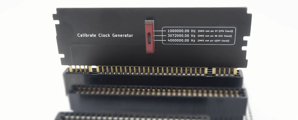
This time, I made a clock generator calibration board for Cartreader (Cartridge Reader).
Since it is used in Cartridge Reader, which is an retrogame damper, please also read the story about how I made “Cartridge Reader Alter”.
 Cartreader 魔改造!? Cartridge Reader Alterをつくったよ
 What is the clock generator doing?
Now “clock generator module” is connected to Cartreader (Cartridge Reader).
What is it? It is mainly used to unlock cartridges that use SNES (SFC) enhancement chips and to dump the EEPROM of the Nintendo64.
This “unlocking the cartridge using the SNES (SFC) enhancement chip” is quite hard and sometimes the dump fails, but the success rate can be increased by increasing the clock generator frequency closer to the specified value.
Clock generator calibration?
How to calibrate the clock generator is described in the Cartreader wiki.
Once the calibration function was loaded press one end of a jumper wire against SNES slot pin 43(A18/BA2) and the other end of the wire against one of the following pins and it should read those values:
- 3072000.00 Hz when connected to SNES slot pin 56(CIC Clock)
- 4000000.00 Hz when connected to SNES slot pin 1(EXT Clock)
- 1000000.00 Hz when connected to SNES slot pin 57(CPU Clock)
It’s like this… 🤔
…but when I try to actually do it, it’s like, “Let’s see – this pin is…40…41…?” and you get lost in your current location😥
It is quite difficult to count, so this time we have created a board to assist in this calibration process.
Order PCBs
Again, we ordered from JLCPCB.
You can get a $54 coupon for new registrations only through the link 👆🏻👆🏻👆🏻
You can also follow JLCPCB Japan (@JLCPCB_Japan) on Twitter and send a DM to get an additional $10 coupon.
It’s cheap, fun, and easy to make boards, so give it a try!
The thickness of this board was changed to 1.2mm since it will be used in a SNES (SFC) slot.
It was over the weekend, but it was shipped in about 3 days.
Arrival of PCB
After crossing the ocean, they arrived safely.
The board we ordered this time looks like this.

It will be like attaching a switch component in the center and switching it.
Components
So, here is the switch to be installed.

Silk printed so that the frequency to be set can be confirmed at the position where the switched.

Now, let’s install it quickly!
soldering
Solder the switches to the board.
This time it is easy since there are only four points, but I took care not to slant the components.

Now that the installation is complete, let’s actually check it with Cartreader (Cartridge Reader).
Change Cartreader (Cartridge Reader) settings
Cartreader (Cartridge Reader) has the clock generator calibration function turned off by default.
Therefore, it is necessary to follow the same procedure as updating the sketch, but with some changes to the sketch before writing it to the Arduino.
Since we are here, we will first download the latest version (V10.2 at the time of writing) of Cartreader (Cartridge Reader).
After downloading, make changes to “Cart_Reader.ino”
First, change the hardware version.
Since my current environment is Cartreader (Cartridge Reader) Alter, I set it to HW3.
Remove // (comment out) before #define HW3.
//******************************************
// !!! CHOOSE HARDWARE VERSION !!!
//******************************************
// Remove // in front of the line with your hardware version
// #define HW5
// #define HW4
#define HW3
// #define HW2
// #define HW1
// #define SERIAL_MONITOR
Then, enable the calibration function.
Remove // (comment out) before #define clockgen_calibration
// Use calibration data from snes_clk.txt
#define clockgen_calibration
After editing, write the sketch to Cartreaduino 2560 connected to Cartreader (Cartridge Reader) Alter
Let’s try it
So, we are ready to go.
First, insert the calibration support board we have created into the SNES (SFC) slot of the Cartreader (Cartridge Reader) Alter.

Then, turn on the Cartreader (Cartridge Reader) Alter and select
SNES/SFC (CLK0+1) → Calibrate Clock
and proceed to calibration.

This is what the initial value looked like at 1000000.00 Hz. There is an error margin because of the continuous fluffy oscillation, but it is off by about 200 Hz.
Now let’s try the actual operation and calibration.
Here is how it is operated.
Left button (once): Decrease correction value
Right button (once): Increase correction value
Left button (twice): Decrease adjustment value (1000→100→10…)
Right button (twice): Increase adjustment value (10→100→1000→10,000…)
Press and hold the button: Save the correction value.
By increasing the adjustment value, it is possible to add 1000 increments with a single press of the right button, or conversely, by decreasing the adjustment value, it is possible to adjust the value by 10 increments.
As you increase or decrease the value, if it fits well at 1000000.00 Hz, switch to 3072000.00 Hz and see what happens… and so on until you get a good value.
complete!
Around the correction value of 222110, I decided to finish the adjustment because the values were roughly correct.
After this, I actually tried a game with an SFC SA-1 chip (Kirby Super Deluxe) and was able to dump it with no problems!
◽◽◽
So this time we talked about making a clock generator calibration board for Cartreader (Cartridge Reader).
We will distribute the board data (Gerber) as soon as it is ready, so if you like, you can actually order it from JLCPCB and try it out.
I hope to see you again next time you have a chance to read it~👋🏻


